Foreword
The days when the domains such as IT, factory automation, electricity grid were placed on islands with no, or very limited connectivity are gone by. In today’s world information technologies are becoming an indispensable factor for almost every walk of life, and the key enabler of this process is exchange of information. Proliferation of Ethernet based standards for industrial automation, energy market and others(home automation, IoT), have created the possibility to integrate devices and subsystems theoretically belonging to different galaxies.
This article describes a solution for how to integrate Profinet devices into the smart grid with the use of IEC 61850, or vice versa, and how to plug intelligent electronic device (IED) into the Profinet network.
Industrial part
A detailed description of Profinet is out of the scope of this article, but in order to simplify the understanding of the solution put forward below, some basic information will be provided here. The two main types of Profinet devices are the Controller and IO Device. A Controller is responsible for identifying devices available in the subnet and establishing connections with them. Once the connection is established, Controller and IO device exchange data on periodic basis, with cycle time being a power of 2 (1, 2, 4, 8, 16, 32…512 milisec). Controller and IO device send the cyclic data to the other side independent of each other, which means that even when some frames are not received, outgoing data is sent to the peer, with the cycle time agreed during connection establishment. Information in Profinet networks is organized into modules. Modules could be input,output or input/output. Input always means the data sent from the IO device to the controller and output is the data sent from the controller to the IO device. In every cycle, data comprised by all configured modules is sent, so usually it must fit into the Ethernet MTU (1500 bytes).
Beside cyclic data Profinet also defines alarms which cold be transmitted by both sides to notify the peer of some anomalies and record data, which are read or written by the controller in a request / response manner. The size of record data is not limited by Ethernet MTU.
Grid side
IEC 61850 is an international standard describing data models and communication services for power grid devices also known as IEDs (intelligent electronic device). Three most important protocols utilized by the IEC 61850 standard are Manufacturing Message Specification (MMS), Generic Object Oriented Substation Event (GOOSE), Sampled Values (SMV).
Control centers like SCADA systems communicate with IED using a client / server model with MMS protocol, and this is often referred to as vertical communication. IED devices installed within a substation can communicate with each other according to the publisher / subscriber scheme, using GOOSE or SMV multicast protocols which are specified by the standard. This is usually called horizontal communication.
The data model of IED is a hierarchical structure consisting of logical devices, logical nodes, data objects and data attributes. Data objects and data attributes can be grouped into the data-sets, which provides the basis for generation of reports, GOOSE or SMV messages. Values of the data model attributes could be modified either by IEC 61850 clients issuing MMS write requests to the server, or by the IED application running on the device in response to some events, such as a change of measured current or voltage, or a received GOOSE message from another IED in the system.
Gateway
There are several ways (some very wired…) how to project the Profinet domain into the IEC 61850 data model, however it is important to meet requirements like: flexibility, performance, ease of deployment or customization. Since the size of Profinet input/output modules may vary from 1 to several bytes (64 or more) bytes, assuming that one module (input or output) would map to one IED attribute would be an oversimplification and thus a serious limiting factor.
The solution by JPEmbedded is simple, yet flexible and it allows to map any subset of cyclic data (both inputs and outputs) to IEC 61850 data model attributes and record data into the IEC 61850 files. As the output variables are updated by the Controller, values of IEC 61850 attributes are set, which might result in some actions like generation of sampled values, GOOSE messages or reports, depending on the configuration of the IED by the client(s).
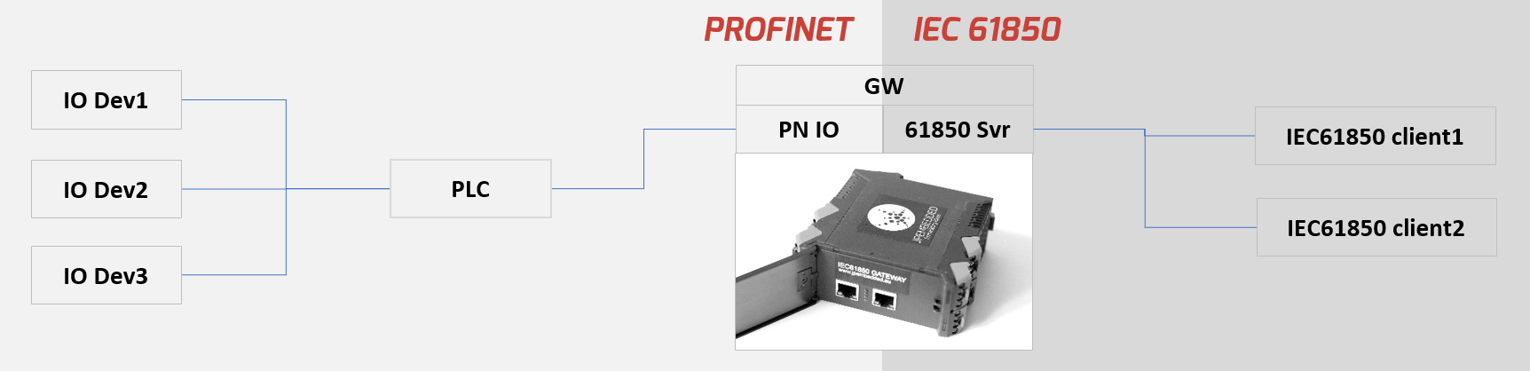
The graphic below shows the gateway along with the devices it is talking to.
The details of the data mapping and implementation are described below.
Maping of data
As described above, Profinet cyclic data is comprised of a number of input or output modules which are configured at the IO device when connection is established. All input modules assemble the content of the frame sent in every cycle to the controller and all output modules of the IO device are updated with the data in the frame received from the controller. User can arbitrarily map the whole or a part of Profinet module to the value of attribute of the IED data model. Of course the mapping must be done with some basic awareness of data types, e.g. mapping of 1 byte to float32 attribute probably does not make sense. The rules of mapping of Profinet module data into the IED attributes are summarized in the table below.
Lets assume that data model of IEC 61850 server is mapped to input module X consisting of e.g. 16 bytes Ib0 … Ib15 and and output module Y consists of 16 bytes Ob0 to Ob15.
The details of the data mapping and implementation are described below.
Mapping to boolean
In case of both input data and output data boolean attribute is mapped to one byte specified by the byte offset.
Mapping of integers
When mapping output data to IEC 61850 integer attribute, first integer value is created based on offset of the byte in the module data, length of the mapped values and endiannes. E.g. if offset is 8 and length is 4, depending on selected endiannes the integer value is created as:
Big endian:
ival = (Ob8 << 24) + (Ob9 << 16) + (Ob10 << 8) + Ob11
Little endian:
ival = (Ob11 << 24) + (Ob10 << 16) + (Ob9 << 8) + Ob8
Than the value is assigned by the gateway application to the attribute which reference is provided in the mapping.
In case of mapping of integer attributes to input data modules, first it is checked if attribute value fits into the number of byte specified by the mapping. If attribute value is too high, Profnet input data is not updated (e.g. mapping of value 25001 to two bytes) and status of the the Profinet input module is set to bad. Otherwise input data bytes are updated, according to the mapping parameters, e.g. if offset is 6, length 2 and value of mapped integer attribute 261 bytes 2 and 3 aew set for big endian as:
Ib2 = 1, Ib3 = 5
and for little endian:
Ib2 = 5, Ib3 = 1
Mapping of floats follows to same rules as mapping of integers described above with the assumption that length of mapped bytes (in both ways) must always be 4.
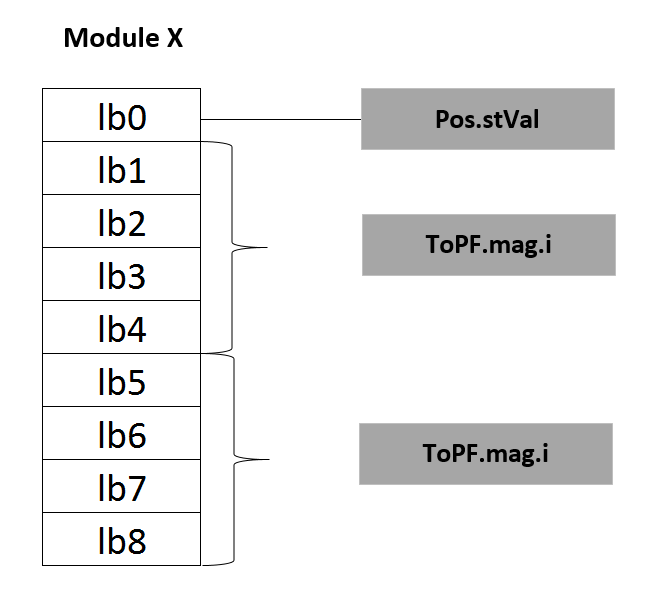
So assuming that 3 attributes
- Gway/XCBR1.Pos.stVal – boolean, 1 byte, offset 0
- Gway/MMXU1.TotPF.mag.i – integer, 4 bytes, offset 1
- Gway/MMXU1.TotPF.mag.f – float, 4 bytes offset 5
layout of input module X bytes will be showed on the picture below.
Mapping of record data
Bigger chunks of Profinet information are called data records. Usually their content is not updated very often (unlike cyclic data), but they could be several kilobytes in size. Mapping them to data model attributes doesn’t make sense, but IEC 61850 journal files seem to be good counterpart. Journal files could be read or written by an IEC 61850 client more or less the same way the record data is read or written by Profinet controller. Again, the user must be aware that some records are mandatory by the standard and they should contain specific, well defined content. So writing them with the IEC 61850 client shall not be allowed, in which case, they could be mapped to read-only journal files. With vendor specific record data, the IEC 61850 side of the gateway should be able to both read and write the content of the file (and associated data record). Each Profinet data record is addressed by the index which are mapped to the IEC 61850 journal file path.
The key to make it generic – XML
The data model and features of IED are defined by SCL file called Configured IED Description (CID). SCL is an XML schema and its structure is defined by the standard. The definition of the file could be customized using a ‘Private’ element and this is how the data model attributes are mapped into Profinet input/output modules.
So the advantage for the end user is that the only configuration task is to prepare a CID file for the device (which must be done anyway) with private section, mapping Profinet to IEC 61850. Then the file will be uploaded to the gateway using a web browser, and the gateway is ready for action. Of course, PN modules mapped to the IEC 61850 data model must be configured on the device by the controller. The other option would be to define the structure of the Profinet IO device in the CID file so that the modules could be plugged into the slots during initialization of the device rather than during connection setup. There don’t seem to be any obvious advantages of this option, and it seems to be an additional overhead and yet another possibility for the user to do something wrong…
The example part of CID file mapping IEC 61850 data model to Profinet module X in slot 1, subslot 1 is shown below:
<Gway>
       <Fbus type="pn" addr="10.0.0.153:1883" />
       <Signal>
         <Ref1 type="in" data="bool">GWay/XCBR1.Pos.stVal</Ref1>
         <Ref2 type="in" data="bool" size="1" offset="0">1/1</Ref2>
       </Signal>
       <Signal>
         <Ref1 type="in" data="int32">GWay/MMXUA.phsA.cVal.mag.i</Ref1>
         <Ref2 type="in" data="int32" size="4" offset="1">1/1</Ref2>
       </Signal>
</Gway>
Implementation
There are at least two real life scenarios in which JPEmbedded’s solution could be deployed in the field and both of them are described in detail below. Let us know which one seems better suited for your needs.
External GW
Lets start with the easier way, which is to plug device with nice housing (see the picture 1) and two Ethernet ports to your Profinet network. Along with the device JPEmbedded provides sample CID and GSDML files. All you have to do is customize the CID, by defining data model for you IED, and map the attributes of the model to inputs and outputs of the Profinet IO device side. The name of the Profinet IO device and its IP address could also be assigned via CID file. Then the device is ready to establish application relationship (AR) with the controller, at which point all the modules are plugged into the slots. The gateway features a two port Ethernet switch, which could be configured to optimize traffic on both sides of the gateway (e.g. multicast and broadcast traffic from one external port are not forwarded to the other external port). After connecting with IEC 61850 client(s), user should see changes of attribute values as a result of updates of Profinet IO device output modules.
Software GW
The other option is to implement the gateway functionality in the customer device. This could be done using libraries provided by JPEmbedded. It requires a bit more effort but on the other hand it offers much more flexibility in terms of features, which could be implemented by gateway application. E.g. on the Profinet side, custom alarms might be triggered or application specific processing of the values of IED data model attributes, which is transferred to the controller as cyclic input data. The fulfillment of certain requirements by the customer hardware could be yet another reason to implement the software version of the gateway.
If you have any comments or questions we encourage you to reach out to us!