The IEC 61850 standard is becoming increasingly popular in the energy sector, gaining significant market traction. As this trend continues, integrators and device manufacturers are increasingly seeking solutions to bridge the gap between older protocols, such as Modbus, and the IEC 61850 standard. This growing demand for compatibility solutions underscores the importance of Modbus to IEC 61850 protocol converters, enabling seamless integration and enhancing the interoperability of diverse systems within the industry.
What is the IEC 61850 standard?
The IEC 61850 is an international standard for communication networks and systems in electrical substations. It was created by the International Electrotechnical Commission (IEC) to standardize communication and data sharing between different devices within a substation. This ensures that equipment from various manufacturers can work together seamlessly.
The main goals of IEC 61850 are to improve the efficiency, reliability, and safety of electrical substations. It achieves this by defining how data should be modelled and exchanged between devices such as transformers, circuit breakers, merging units, and protection relays.
Key features of the IEC 61850 standard include:
- Data Modelling: It uses logical nodes to represent different functions or equipment within the substation, and data objects to represent specific pieces of information like measurements, states or statuses.
- Communication Protocols: The standard specifies several protocols for data exchange, including:
- MMS (Manufacturing Message Specification) for real-time communication.
- GOOSE (Generic Object-Oriented Substation Event) for fast, reliable event-driven communication.
- Sampled Values (SV) for transmitting time-critical measurement data.
- System Configuration: IEC 61850 provides guidelines for configuring and managing substation systems using an XML-based language called System Configuration Description Language (SCL).
The standard offers many benefits, such as enhanced efficiency, reliability, security, and the ability to easily integrate new devices into existing systems. It is widely used in electrical substations and other parts of the power system, like power plants and wind farms, to ensure smooth and efficient operation.
What is the Modbus communication protocol?
Modbus is a communication protocol developed in 1979 by Modicon (now Schneider Electric) for use with its programmable logic controllers (PLCs). It is widely used in industrial environments to enable devices to communicate with each other.
Modbus is designed to connect various devices on the same network, such as sensors, actuators, and controllers. It can work over several types of physical media, including serial lines (like RS-232 and RS-485) and Ethernet.
The protocol uses a master-slave architecture. The master (or client) initiates communication by sending requests to the slave (or server) devices, which then respond. Modbus supports multiple types of data, including single-bit values (coils and discrete inputs) and 16-bit values (holding registers and input registers).
There are different modes of Modbus communication:
- Modbus RTU: Uses binary data for serial communication.
- Modbus ASCII: Uses ASCII characters.
- Modbus TCP/IP: Encapsulates Modbus messages within TCP/IP packets for Ethernet communication, making it suitable for modern networked environments.
Modbus is known for its simplicity, ease of implementation, and wide acceptance in the industry. However, it has limitations, such as basic error handling and lack of support for complex data structures. Despite these limitations, it remains a popular choice for connecting industrial devices due to its reliability and ease of use.
What is the Modbus to IEC 61850 converter?
A Modbus to IEC 61850 protocol converter is a device or software tool that enables communication between systems using the Modbus protocol and systems using the IEC 61850 standard. This type of converter enables interoperability between devices that uses not compatible protocols, facilitating seamless data exchange and integration within industrial and utility networks.
Typical Applications of converter:
- Substation Automation:
- Integrating older Modbus-based devices (e.g., meters, sensors) into IEC 61850-based substation automation systems.
- Facilitating communication between protection relays, control systems, and monitoring devices.
- Industrial Automation:
- Connecting Modbus-based industrial controllers and devices with IEC 61850-based energy management systems.
- Enabling seamless data exchange between factory automation systems and utility networks.
- Smart Grid:
- Enhancing the interoperability of smart grid components by bridging the communication gap between different protocols.
- Supporting advanced grid management and monitoring through integrated data from various sources.
Benefits of using Modbus to IEC 61850 protocol gateway are:
- Enhanced Interoperability. Enables the integration of diverse devices and systems, ensuring smooth communication and operation across different protocols.
- Cost-Effective Integration. Allows the use of existing Modbus-based equipment within modern IEC 61850 systems, reducing the need for complete system overhauls.
- Improved System Efficiency. Facilitates real-time data exchange and improved decision-making in automated systems.
- Future-Proofing. Provides a pathway for upgrading legacy systems to modern standards without immediate, wholesale replacement.
- Security. May provide encryption that protects data transmitted between devices. This encryption helps prevent unauthorized access, eavesdropping, and data breaches. Protocols such as Modbus that do not use secure protocols are vulnerable to interception and tampering by malicious actors.
- Link Redundancy. Some gateways offers redundancy protocols such as PRP or HSR.
In summary, a Modbus to IEC 61850 protocol converter is a crucial tool for achieving interoperability and efficient communication between different generations of industrial and utility devices, supporting the integration of legacy systems into modern automation and smart grid infrastructures.
What are the main types of Modbus to IEC 61850 converters?
Modbus to IEC 61850 protocol converters come in various physical forms to suit different application requirements and environments. Here are the common physical forms you might encounter:
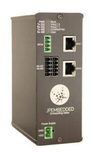
- Standalone converters. Designed as independent units that can be placed on a desk, mounted on a wall, on a DIN rail or fitting into standard 19-inch equipment racks. They are usually easy to install, typically housed in robust enclosures. Used in control panels, switchboards in substations, data centres, large control rooms, but also in small-scale installations, testing, proof of concepts, and temporary setups.
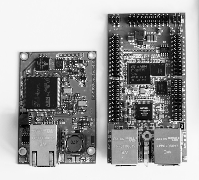
- Embedded converters. Dedicated to be integrated into other devices or systems, these converters come as modules or circuit boards. They are customizable and can be embedded directly into devices like RTUs (Remote Terminal Units), Protection Relays and others. Suitable for OEMs (Original Equipment Manufacturers) who need to add Modbus to IEC 61850 conversion capabilities to their products.
- Software converters. They are delivered as dedicated software components in the form of binary files or applications. Due to their form, they can be integrated into a very wide range of products, including industrial and energy devices, computer and cloud applications. Suitable for OEMs and Software companies.
How to configure gateway and map Modbus registers to IEC 61850 data attributes?
Mapping Modbus registers to IEC 61850 data attributes involves creating a correspondence between the data model used in the Modbus protocol and those in the IEC 61850 standard. This allows data from Modbus devices to be interpreted and used by IEC 61850-compliant systems.
Following is a step-by-step guide on how to perform example mapping:
1. Identify Modbus data points
- Modbus Registers: Determine which Modbus registers (e.g., coils, discrete inputs, holding registers, input registers)needs to be mapped.
- Data Types: Identify the type of data stored (e.g., integer, float, bit).
2. Identify IEC 61850 Data Model nodes
- Logical Nodes (LNs): IEC 61850 uses logical nodes to represent specific logical, functional unit within a substation.
- Data Objects (DOs): Each logical node contains data objects, which represent various attributes, states or statuses of the equipment.
- Data Attributes (DAs): Data objects have data attributes, which are the actual values(e.g., measurements).
3. Create a Mapping Plan
- Mapping Table: Create a table or spreadsheet that lists Modbus registers alongside their corresponding IEC 61850 logical nodes, data objects, and data attributes.
- Define Correspondence: For each Modbus register, specify the corresponding IEC 61850 logical node and data attribute. This involves understanding the semantics of both data points to ensure correct mapping.
4. Configure the Protocol Converter
- Run Configuration Tool. Use the configuration tool provided by the protocol converter manufacturer. This is typically a software application with a graphical user interface (GUI) or a web-based interface.
- Input Mapping Information. Enter the mapping information from your plan into the converter’s configuration tool. This usually involves specifying the source (Modbus register) and destination (IEC 61850 data attribute) for each data point.
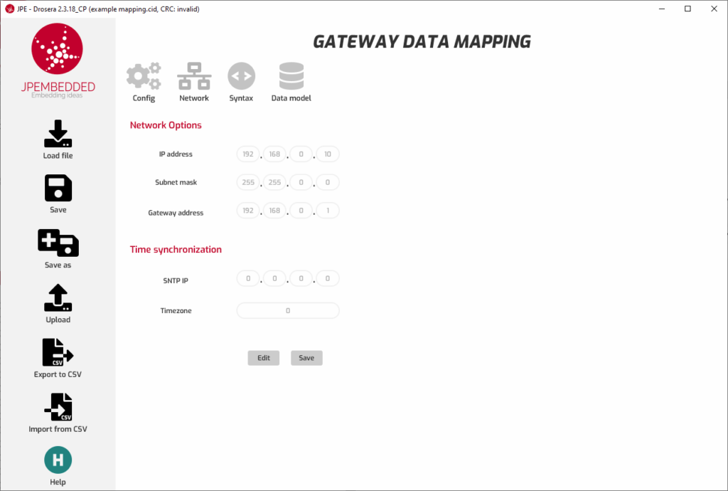
- Set Communication Parameters. Ensure that communication parameters such as IP addresses, port numbers, baud rates, and device IDs are correctly set for both Modbus and IEC 61850 networks.
5. Save configuration. Save the settings and deploy them to the converter.
Example Mapping
Here’s a simplified example to illustrate the mapping process:
Modbus Data Points
- Holding Register 40001: Current in phase A (integer).
- Coil 00001: Breaker Position status (on/off).
IEC 61850 Data Model
- Logical Node: MMXU1 (Measurement Unit)
- Data Object: A (Current)
- Data Object: phsA (phase A)
- Data Attribute: cVal.mag.f (real RMS value of the current in phase A)
- Data Object: phsA (phase A)
- Data Object: A (Current)
- Logical Node: XCBR1 (Circuit Breaker)
- Data Object: Pos (Position)
- Data Attribute: Pos.stVal (Position status)
- Data Object: Pos (Position)
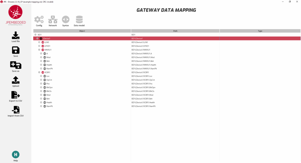
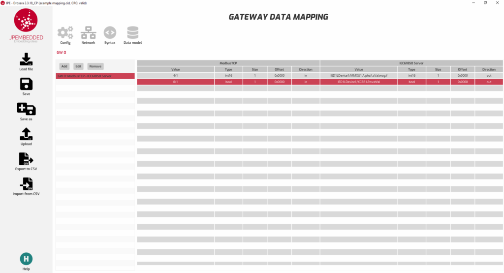
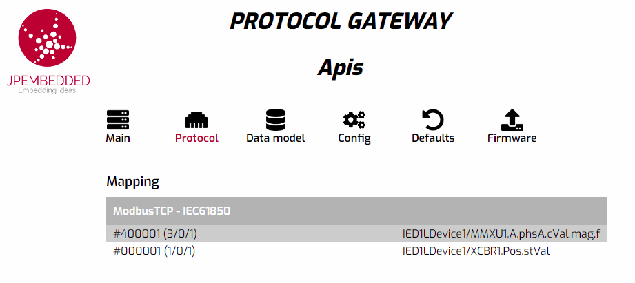
Mapping Table

Examples of mappings in the Modbus to IEC 61850 protocol converter configuration application
How much does the Modbus to IEC 61850 converter cost?
The price of a Modbus to IEC converter can vary widely based on several factors, such as the physical form of the converter and supported features like PRP redundancy or cybersecurity. Additionally, the price is strongly correlated with the quantity ordered, especially in the case of OEM modules.
If this topic interests you and you would like to learn more about protocol converters, please contact us!