Standard IEC 61850, developed by the International Electrotechnical Commission (IEC), defines a data and communication model for devices in electric power management systems. However, the standard is not limited solely to the power industry, and it finds application in various fields.
One significant aspect of IEC 61850 is its facilitation of an engineering process that enables the interchange of standardized information among different tools. Initially designed for configuring the communication and data model of devices according to the IEC 61850 standard, the scope of the IEC 61850 engineering process has evolved over time.
The System Configuration Language specified by IEC 61850 for the configuration of electrical substation devices, comprises several components:
- Header: This segment serves to identify the version and other fundamental details within an SCL configuration file.
- Substation: This section addresses the various components of a substation, encompassing diverse devices, interconnections, and additional functionalities. Elements include power transformers, voltage levels, bays, general equipment, and conducting equipment like breakers. Logical nodes representing functionality related to objects in the substation are referenced from this substation part.
- Communication: This division focuses on distinct communication points (access points) for reaching different IEDs within the entire system. It encompasses various subnetworks and access points.
- IED: The IED segment outlines the comprehensive configuration of an Intelligent Electronic Device (IED). It includes different access points of the specific IED, logical devices, logical nodes, report control blocks, etc., falling under the IED. It specifies the data that an IED publishes as reports and Generic Substation Events (GSE; categorized into GOOSE and GSSE), as well as the GOOSE/GSSE data from other IEDs that an IED is configured to receive.
- DataTypeTemplates: This defines distinct logical devices, logical nodes, data, and other details separated into various instances. The complete data modeling, following IEC 61850-7-3 & 7-4, is depicted in this section of SCL. It is further categorized into LNodeType, DOType, DAType, and
Depending on the purpose of the SCL file, it is classified into various types, e.g., ICD, SSD, SCD, CID, IID, SED. Following text will focus on a few selected ones that apply to Intelligent Electronic Devices as a brief introduction to the topic.
ICD, CID, SCD, IID – characteristics and differences
IED Capability Description (ICD)
The ICD file outlines the full range of capabilities for an Intelligent Electronic Device (IED) and is provided by the vendor or manufacturer to facilitate the complete system configuration. It encompasses a single IED section and optionally may also include communication and substation sections. The IED shall be named ‘TEMPLATE’. Based on the information in the ICD, the system integrator defines the specific device configuration and then exports it to a CID (Configured IED Description) file.
Substation Configuration Description (SCD)
The SCD file provides a detailed description of the entire substation, encompassing sections related to communication, Intelligent Electronic Devices, and data type templates. In essence, SCD files combine information from both ICD and SSD files (System Specification Description).
Instantiated IED Description (IID)
The IID file specifies the configuration of an IED for a specific project and provides a data exchange format necessary to connect the IED configurator with the system configurator. It exclusively includes data related to the currently configured and include the IED section, the communication section (including parameters), and the templates for IED data types. Optionally, there is a substation section with associations of functions (LogicalNodes) to the single line diagram.
Summarizing, there is a notable distinction between CID (configured IED description) and ICD (IED capability description) files concerning their utilization and the information they encompass. A simplified description of the process of using Substation Configuration Language files according to the IEC 61850-6 standard will be presented in the following paragraph.
SCL – Configuration Process
ICD files encompass a device’s capabilities, resembling a template with a generic depiction of all the functions and objects that a specific device can support. These files are generated by the developer or manufacturer. The ICD file serves as input for a System Configuration Tool (SCT), which the designer employs to construct a Substation Configuration Description (SCD) file containing the substation’s design. The SCD incorporates all the necessary devices for that particular system. The SCT can be utilized to generate an Instantiated IED Description (IID) file from the SCD, providing a description of the functions and objects required by an IED for that specific system. The IID is typically a subset of the ICD in terms of functions and objects, but it also includes configuration details related to the system design, such as report and GOOSE subscriptions.
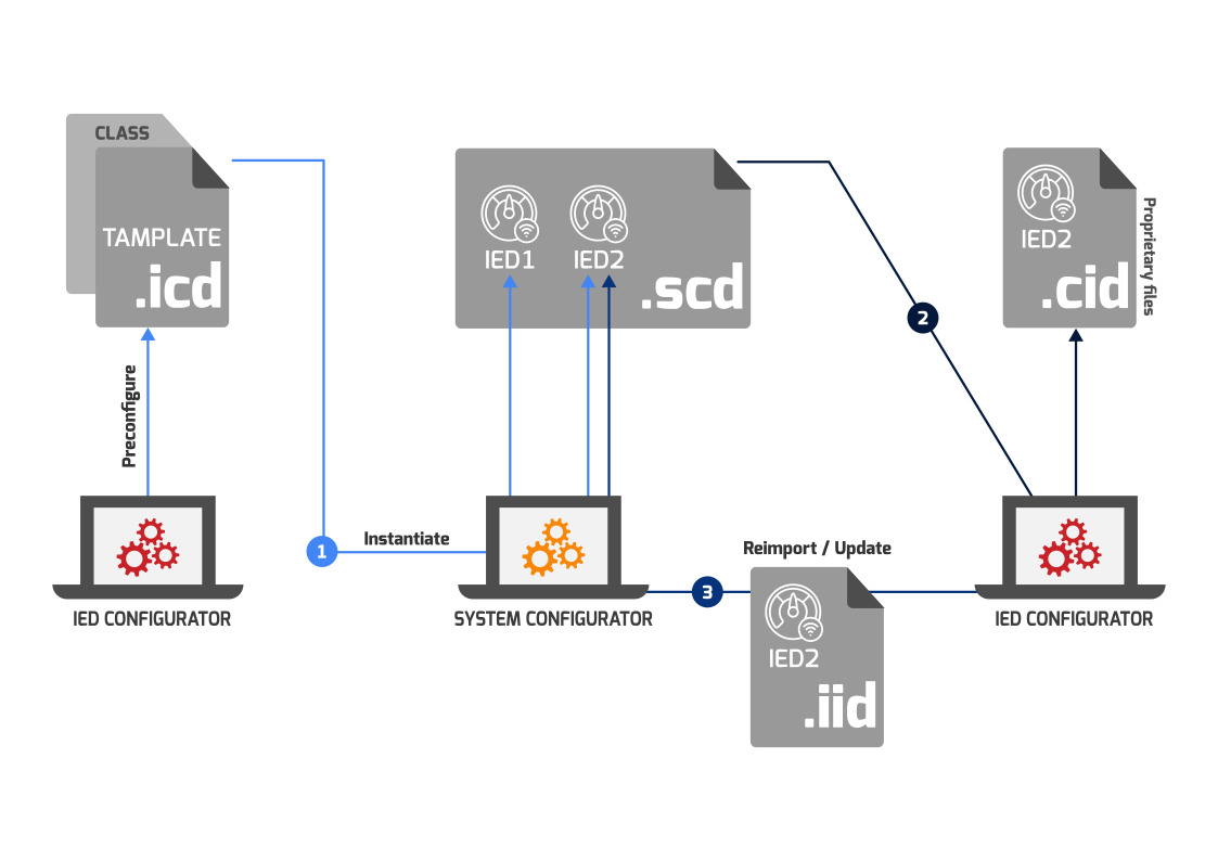
The graphic below illustrates the process of file modification.
In the initial phase of the system engineering process, ICD files are utilized by the system configurator to generate project-specific IED devices tailored to specific needs (1). The next step involves importing the resulting SCD file by the IED configurator for the final configuration of the IED device (2). Any add-ons or customized values can be exported to an IID file and subsequently reintroduced to the system configurator or the next version of the SCD file (3).
Creation of CID and ICD files
If the discussed topic is of interest to you, we encourage you to explore another one of our articles, Creating CID and ICD files isn’t that difficult!
The text showcases the capabilities of one of our solutions – Hedera software, which enables the creation of CID and ICD files. This tool is specifically designed for users of Papilio and Apis communication modules. Its purpose is to maximize the simplicity of the preparation process and seamlessly guide users through the entire configuration in compliance with the IEC 61850 standard. With the help of Hedera application, even individuals not very familiar with the standard can confidently create and edit IEC 61850 data models.
